I needed this to work on the Metcal power supply but it is much more generally useful. It's based around a commercial 50 Ohm 150 Watt resistor built up with a large heatsink and some power metering. It is similar to the one described here.
All images on this page are low resolution versions. Click them for bigger versions.
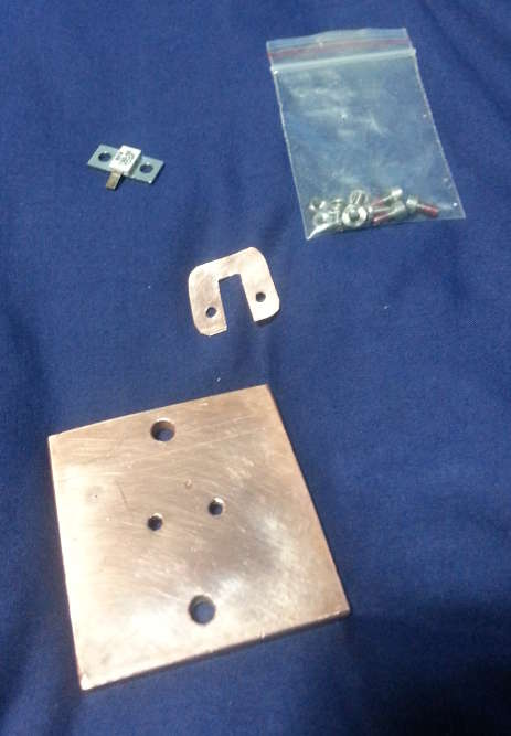
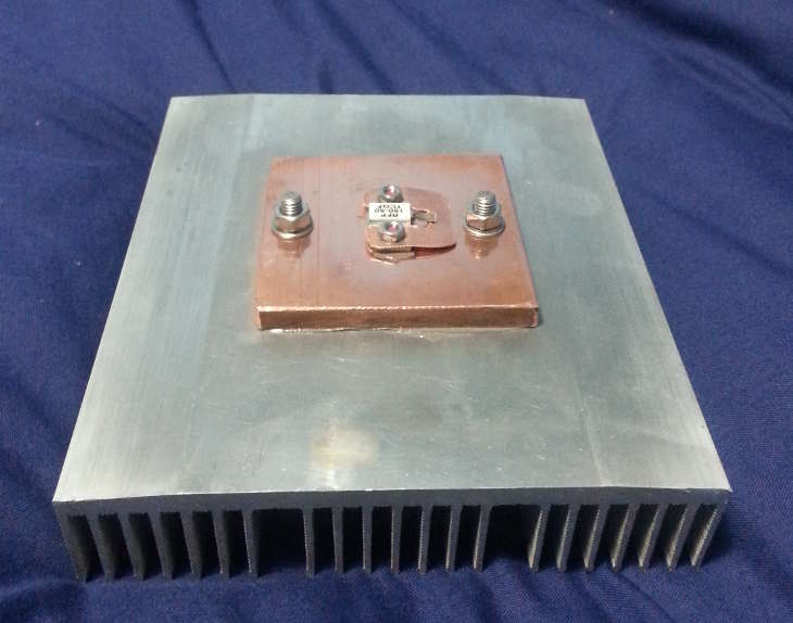
A thick slab of copper is used as a heat spreader. The load resistor is mounted to this with good-quality thermal paste. The C-shaped piece of copper contacts the top surface of the resistor's mounting tab - this is the RF return path. The power resistor itself is a RFP-150-50TCGF, I got this off ebay for £7.00 as new old stock. It's technically obsolete but only because a new version with no beryllia now exists. Please note that if you're prone to licking RF power resistors, using them to stir your tea or dropping them and snorting the dust then I suggest you use a newer design without the BeO.
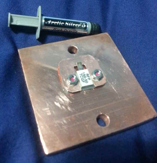
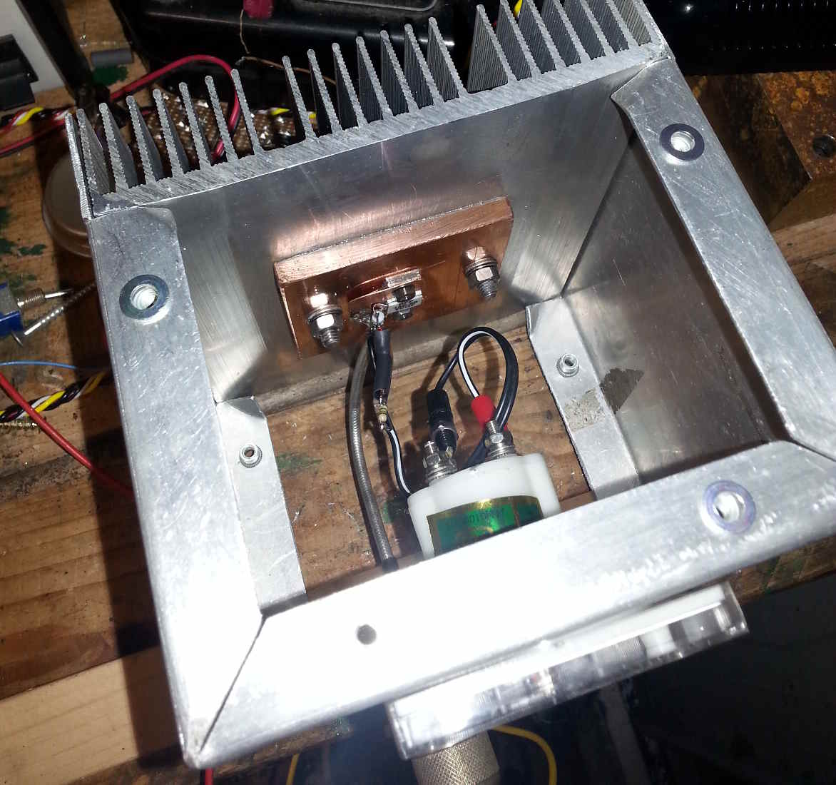
The whole assembly is bolted to a larger aluminium heatsink. A short length of semi-rigid coax with an N-connector pre-fitted is soldered to the copper C shape and to the resistor's silver top contact. Unfortunately I didn't take a photo of this, it's actually quite critical in order to give good high frequency performance. A simple peak detector and scaling resistors for the 100 uA meter movement are also fitted. The peak detector is based around 1N4148 diodes so will only behave up to around 30 MHz but the load itself should be happy well beyond that.
The heatsink forms the back of a folded aluminium enclosure. On the front panel will be the meter, the RF input and terminals to provide DC power to a small fan if needed.
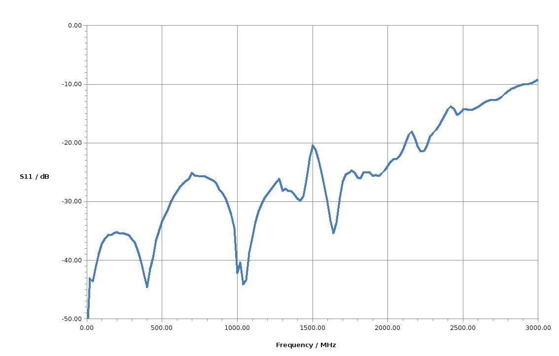
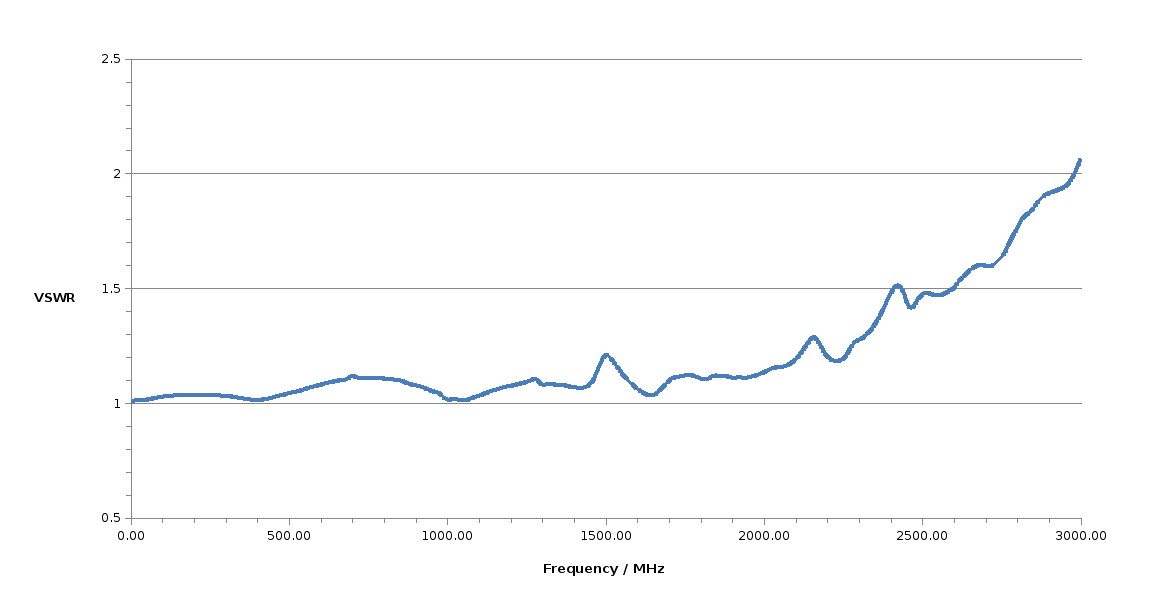
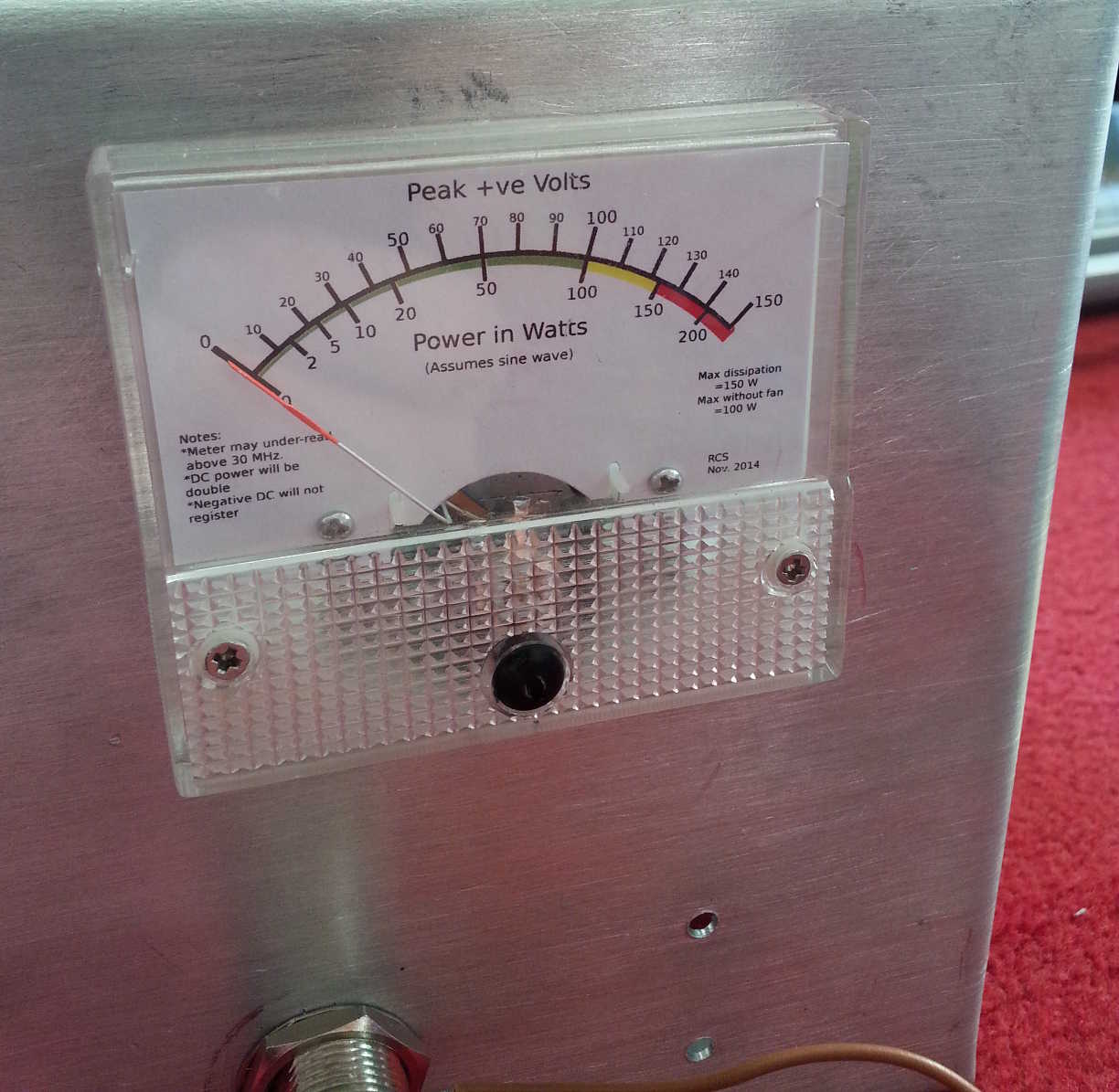
The meter was calibrated with DC to account for meter non-linearity and diode forward drops and then a new scale printed to show both peak voltage and power. Experimentation showed that it was happy with 100W continuous and that only minimal fan cooling was needed for 150W, the maximum rating of the resistor. The colour code on the scale reflects this. Finally S11 was measured on a network analyser and the plot printed and stuck to the side for convinient future reference. It looks a bit shabby in the photos and could probably do with re-printing.
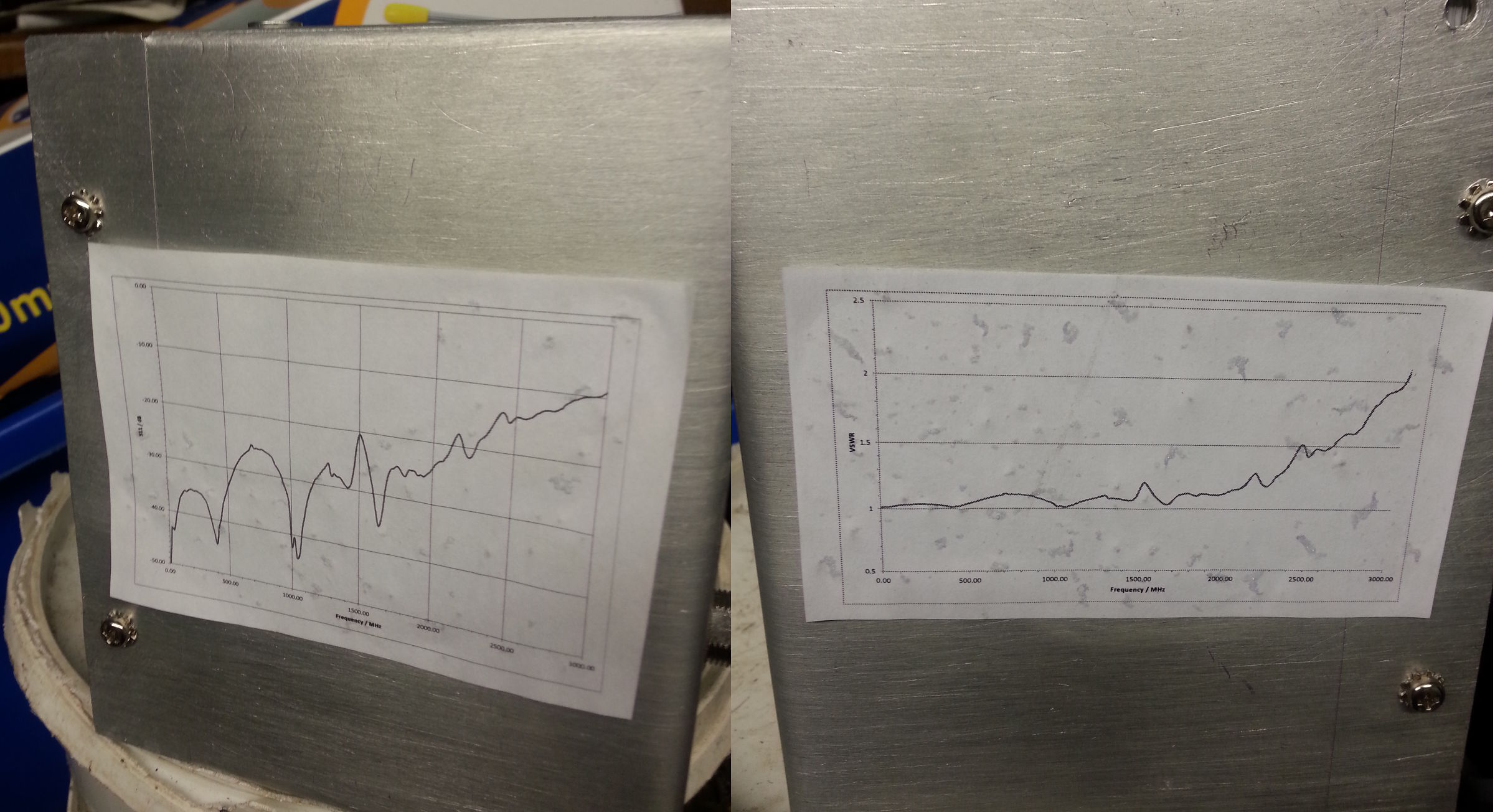
Return loss >20dB (VSWR less than 1.3:1 ) to over 2 GHz, 10dB (2:1) at 3 GHz, I'm pleased with that :-)