Efforts to make a working jet from an old turbocharger

This was inspired by the many other people who have successfully built similar jet engines (see the links page for more details). My own was nearly completed in 2005 but for various reasons did not run until December 2010. As with the trike page click the images for bigger versions.
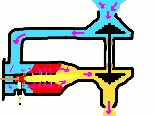
The basic principle on which the jet works will now be described with the assistance of the diagram below (yes, I know it looks like a 3 year old drew it in paint but I don't care, it gets my point across). The main part of the engine is the turbocharger, shown on the right of the diagram, with two turbines. The one at the top draws in cold air from the surroundings and forces it along a pipe to the combustion chamber. Here a quantity of fuel is burnt heating the air and thereby increasing its volume. This hot air then enters the exhaust turbine where it causes it to spin, this is what drives the compressor. After leaving the exhaust turbine the hot gasses leave through a nozzle where they hopefully generate some thrust.
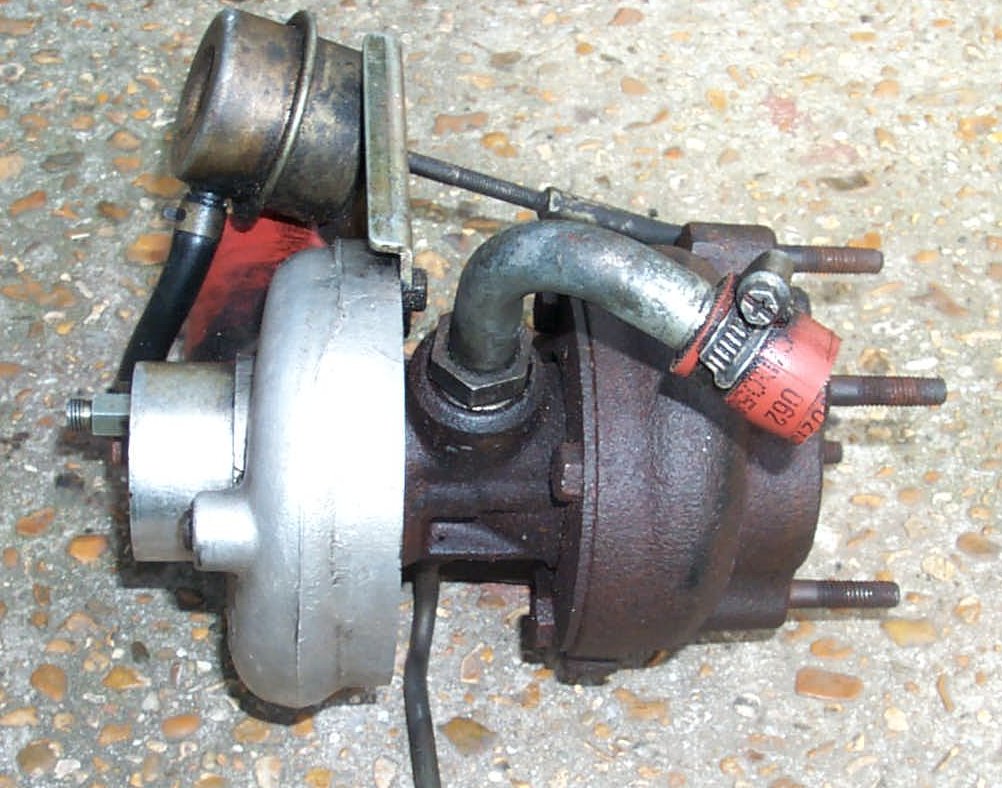
The first step in building one of these beasts is obviously to acquire a turbocharger from somewhere. I didn't have much success looking in scrapyards in my area and ended up buying a used turbo off Ebay for about £20. This turbo is shown below. The shiny silver side is made from aluminium and houses the compressor wheel, the rusty side is made from cast iron to better stand the heat and contains the exhaust turbine. The large pipe at the top is the oil return and the much smaller pipe at the bottom is the high pressure oil feed. This oil not only lubricates the bearings in the turbo but also provides some cooling (larger turbos often have connections for water cooling in addition to this but this one doesn't. The cylindrical thing on top is designed to open the waste gate when the pressure on the inlet reaches a certain level. This allows some of the exhaust gasses to bypass the turbine and crudely regulates its speed. I removed this and held the valve shut with a spring since it has no use on a jet engine
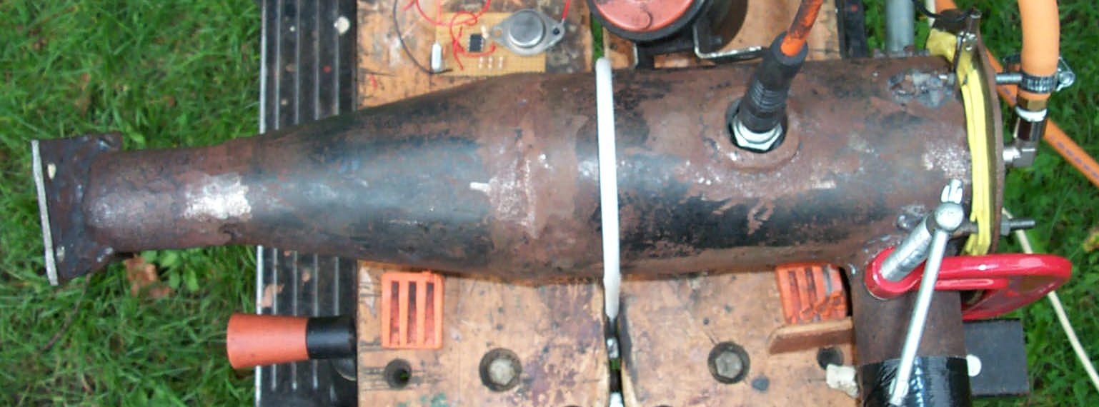
The next major component is the combustion chamber. This must be built and is fairly complex to design and construct, my version of this is shown in the second of the two images above. The left hand end bolts onto the flange on the turbo and the short stub of pipe on the bottom right of the photo is the air inlet which connects to the outlet of the compressor.
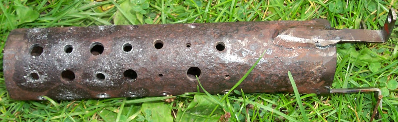
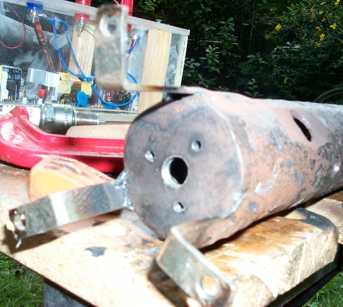
It must mix the fuel with some of the incoming air and burn it efficiently, then this must mix with the rest of the air heating it while lowering the temperature at the outlet to a point where it will not damage the turbine. In order to achieve this the combustion chamber contains an inner burner tube within its shell to burn the fuel and stabilise the flame. For simplicity I decided to use propane as the fuel during testing with the possibility of using a liquid fuel later on for more power. The flametube is the topmost image below. It is made of very thick walled iron tubing, I think it was gas pipe but I found it as scrap so I don't really know. It is capped at one end and open at the other with many holes along its length to admit air for combustion. It has three legs made out of mild steel that support it within the combustion chamber.
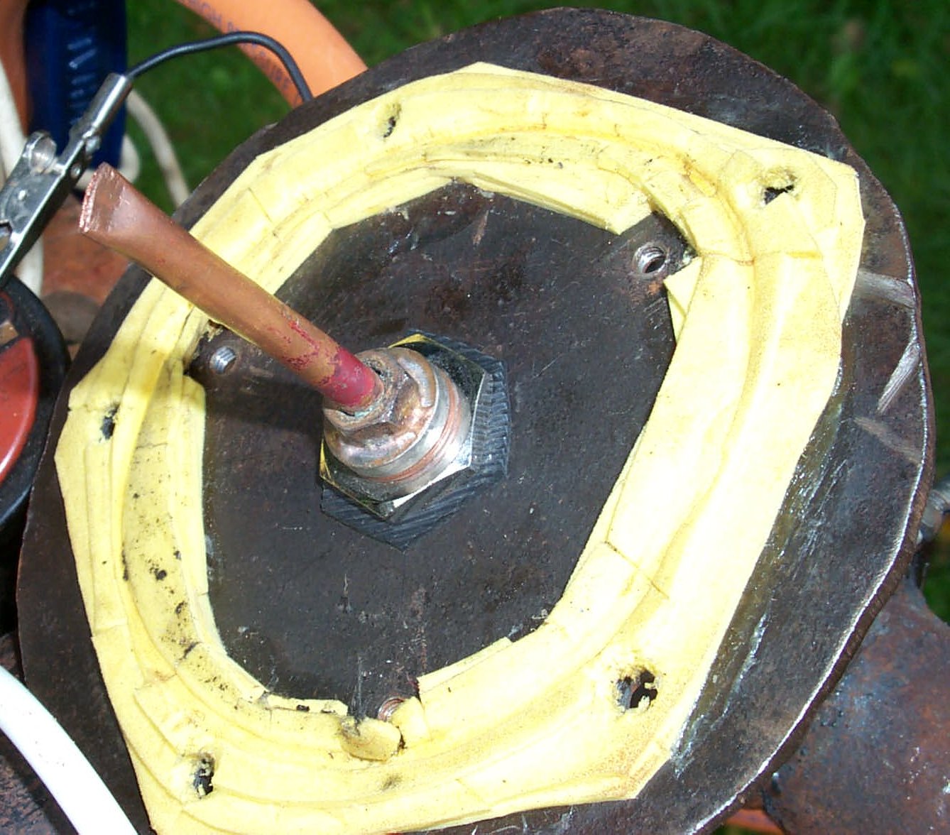
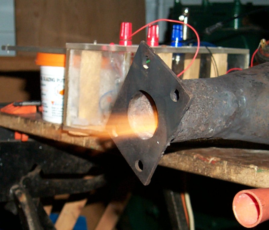
The next picture shows the lid of the combustion chamber. It has a layer of neoprene foam to seal it against the wall of the chamber without too much air leakage. The five large holes are for the bolts that hold it on and the three smaller holes are tapped to accept screws in order to hold the flame tube in place. In the centre of the plate is the fuel injector. This is simply a piece of quarter inch copper tubing with the end squashed flat. It is brazed into a blanking plug of the type normally used to block off unused outlets and also has a nut brazed to it to provide a hexagonal piece by which it can be tightened into place. It screws into a bulkhead mounted fitting. This was done to make it easy to experiment with different injectors.
The last of the three pictures above shows the top end of the flame tube. The fuel injector passes through the large central hole in the end and the gap there together with the three smaller holes provide the air needed for ignition. The big hole in the side of the flame tube is for the spark plug. The spark plug is screwed into the outer shell of the combustion chamber but its tip protrudes through this hole and is used to ignite the gas when starting the jet. more detail on this later.
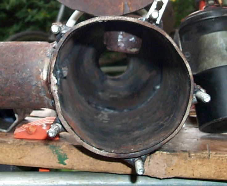
Above you can see the view down the combustion chamber. The wall is made from 2.5mm thick steel plate and I had underestimated how hard this would be to bend. It is made in two parts, one conical and one tubular together with several short stubs of pipe for the inlet and outlet. Looking at the end it becomes clear that it is not completely round but that does not affect its operation in any way. The studs around the outside are 6mm bolts which have been welded on and the bulge that is visible at the top is the mount for the spark plug. The spark plug is sunk into the chamber slightly to put the electrodes in the correct place for ignition. I had considerable trouble locating a tap to cut the 10mm diameter metric fine-thread needed (it is a motorcycle plug) and in the end I decided to just find a nut that size and weld it on. That was also not as easy as it sounded and I ended up using a piece of metal cut from the crank of a scrap childrens bike as it used this thread on the pedals.
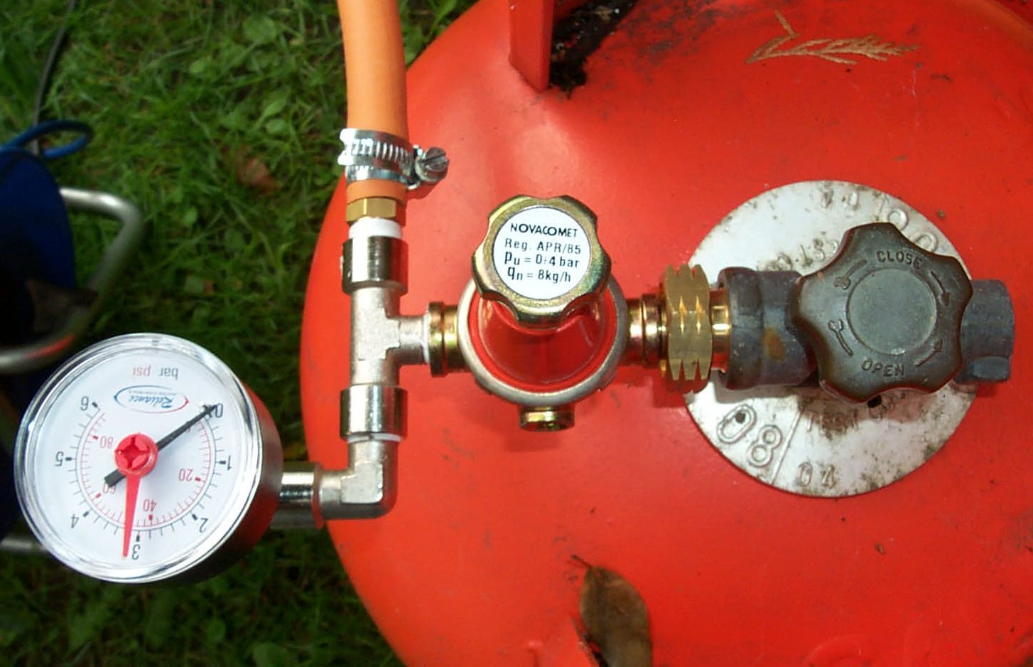
The next picture shows the gas regulator. In use the cylinder valve is opened fully and the knob on the regulator is used to control gas pressure. The regulator claims to be adjustable between 0.5 and 4 bar (7-60 psi) but in practise the range was found to be slightly greater than this. I have not measured fuel consumption so I cannot comment on the 8kg per hour limit of the regulator. There is a pressure gauge fitted to allow accurate control and 2 meters of flexible hose joins the regulator to the fuel injector. This hose was ordered several times larger than needed for the expected flow rates (the company I ordered from questioned this) but the reasoning behind it was that this tube had greater wall thickness and so would be less likely to get damaged. A serious leak such as a cut pipe would likely be disastrous.
This then is the completed combustion chamber with a system for supplying fuel, all it needs now is a source of air and some method of ignition and it can be tested! To provide the air I was originally looking for an old vacuum cleaner that could be reversed but since I was unable to find one I simply modified a normal one to blow rather than suck (I just partitioned it inside and moved the hose to the outlet of the fan, didn't try to reverse the motor or anything).
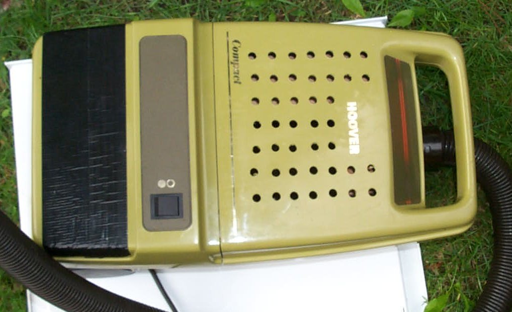
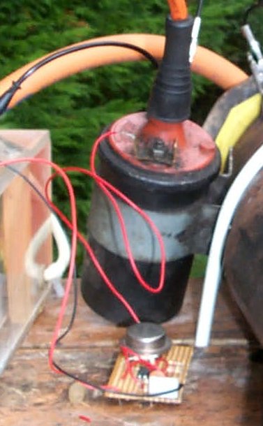
This modified vacuum cleaner is shown above, the black tape is blocking the original vent holes (this is not a very good idea as I discovered afterwards. The heat from the motor tend to loosen the tape and then air leaks out). The other holes are the new air inlet. The second picture above shows the ignition circuit. The electronics on the small board at the bottom of the picture rapidly switches the 12V supply to the coil on and off. I haven't measured it but judging by the buzzing noise the arc makes the switching frequency is in the region of a few kiloHertz. More details on the ignition circuit are available on a separate page.
And now finally, on to the combustion chamber testing - the fun bit! This is not quite the first test, much earlier before the fuel system was built or the blower was acquired I was messing around and decided to see what would happen if I squirted some fuel in it. The air inlet was taped onto the outlet of the compressor and the turbine was spun by means of a vacuum cleaner connected to the exhaust port. The ignition was turned on and a short plastic tube was inserted into the base of the flame tube. I then fed some gas in from a lighter-refill can (butane), there was a loud roaring noise and a blue flame appeared at the end. So I then tilted the can to allow liquid butane to flow through the pipe. FUN! I only did this twice but both times the fuel ignited and resulted in a roaring blue flame that shot 6 to 8 feet across the garage. Total burn time was just a few seconds but the whole combustion chamber was too hot to touch. Anyway - onto the real testing.
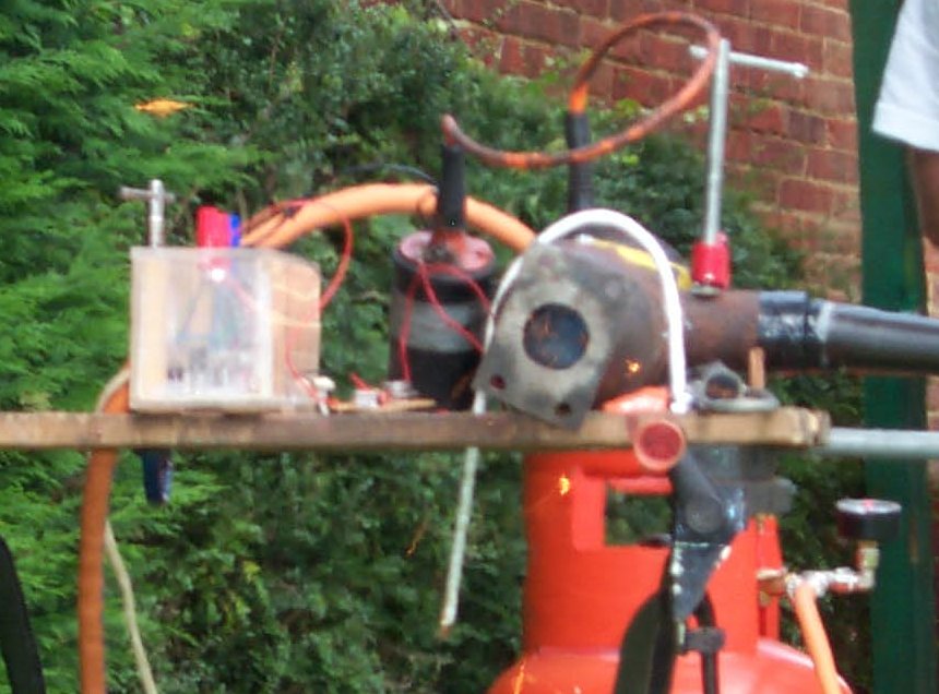
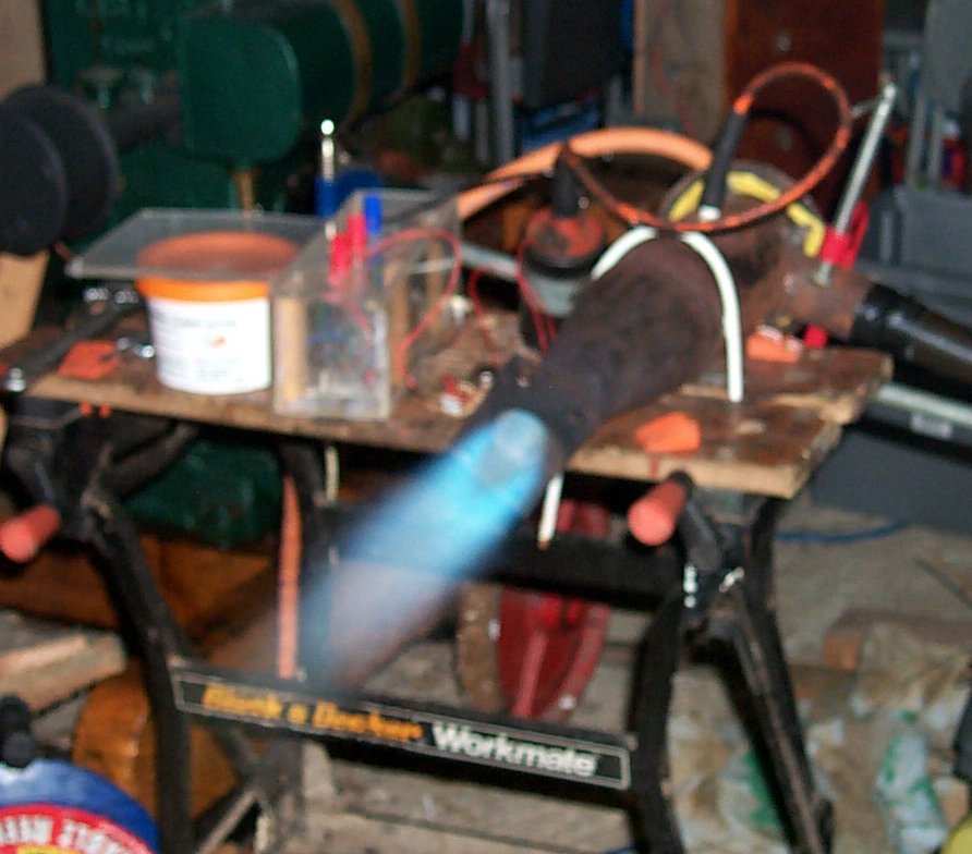
Below you can see the combustion chamber connected up for testing and mounted onto a workbench. I found that I needed to turn the gas flow up considerably to get the correct mixture for it to ignite. I turned off the ignition expecting it to go out but it didn't. Just about visible in the daylight was a blue flame protruding about 4 inches from the end of the combustion chamber, cranking the gas up made this flame over a foot long. We tried turning it off and checking that it re-ignited reliably - once hot it lit instantly without too much of an increase in gas flow. During this whole time I had my dad standing nearby and panicking. Since the flame was barely visible I attempted to measure the length of the flame by holding a piece of wood in front of the outlet and seeing at what distances it would catch fire. Walking across in front of it at a distance of around 15 feet I could feel an amazingly powerful blast of hot air. While doing this I took the second photo in which the blue glow of the flame is just visible due to the darkness inside. It isn't very clear in the picture but parts some parts inside were glowing bright red. Occasionally bright white sparks would fly out of the end of the tube, probably pieces of metal filings and burrs from the holes.

I was quite happy with this but I decided to see if it was possible to add more holes (and hence extra air) to the flame tube so that the flame was shorter and did not protrude from the end of the combustion chamber. This was ultimately a failure since after these modifications I found it impossible to ignite the fuel. I do not believe that this will be a major problem however because in use the airflow from the compressor will be much greater than that delivered by the vacuum cleaner so the flamer should be shorter and more contained anyway.
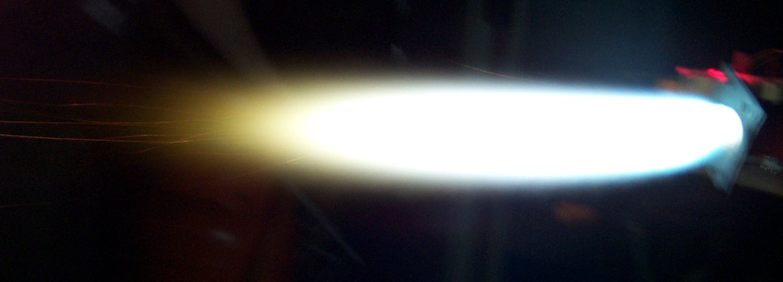
Since the flame hadn't really been visible during the daytime and also because I wanted another go with it another combustion chamber test was conducted - this time at night. You can see the results in the two photos below. The first shows the flame just after ignition, fuel pressure is around 2 bar. the second shows it after it has heated up for a few seconds and the fuel pressure has been cranked up to the max. - just over 4 bar. The air blast is incredibly powerful and one day I may build a thermojet based on this design (basically a powerful engine driven blower with a combustion chamber added to increase thrust by making the air expand).
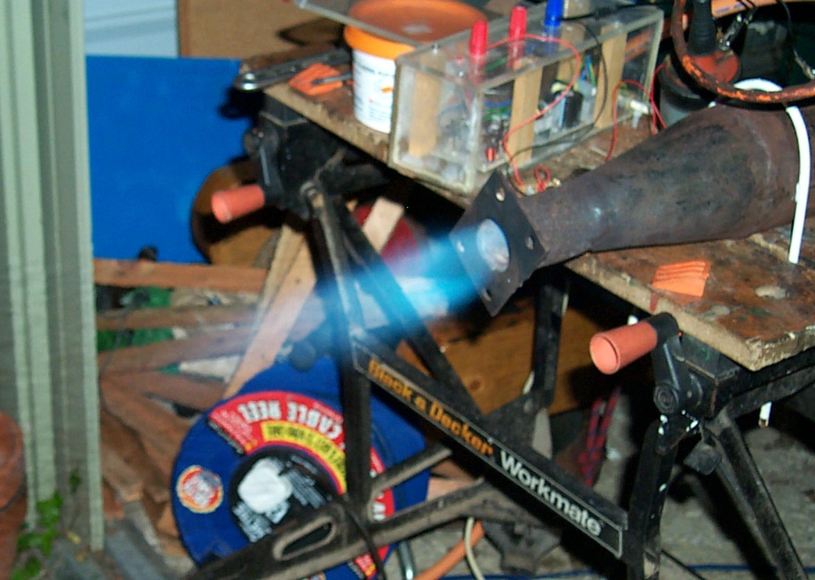
During this I experimented to see how low I could adjust the fuel. I found below a certain pressure it continued to burn but the mixture changed drasticaly and a low yellow flame was produced instead of the roaring blue one. This is not really of any practical purpose but it is interesting to know that combustion is still stable at this low fuel pressure. There is also one picture of the flame with the fuel flow max-ed out and a fairly long exposure to capture the flame. The horizontal streaks in this image are causes by sparks flying from the combustion chamber. Probably more metal filings and crap that had become dislodged. This is more of a fun pic. After we took this we shut down the jet and looked into the exhaust. the whole flame tube was glowing bright cherry red. We tried to get a photo of this but thanks to the flash the red glow was barely visible.
It is interesting to note that in all of these tests the top of the combustion chamber (the bit near the air inlet) remained cold enough to touch. The cooling air was obviously doing its job and in addition to this if it was removing that much heat then it must have attained a high temperature itself, very desirable for this purpose. The white loop that is visible clamping the combustion chamber to the workbench in several of these pictures is plastic coated and began to melt after several minutes use but never became hot enough to burn. I estimate that the temperature at this point was probably around 200 degrees C.
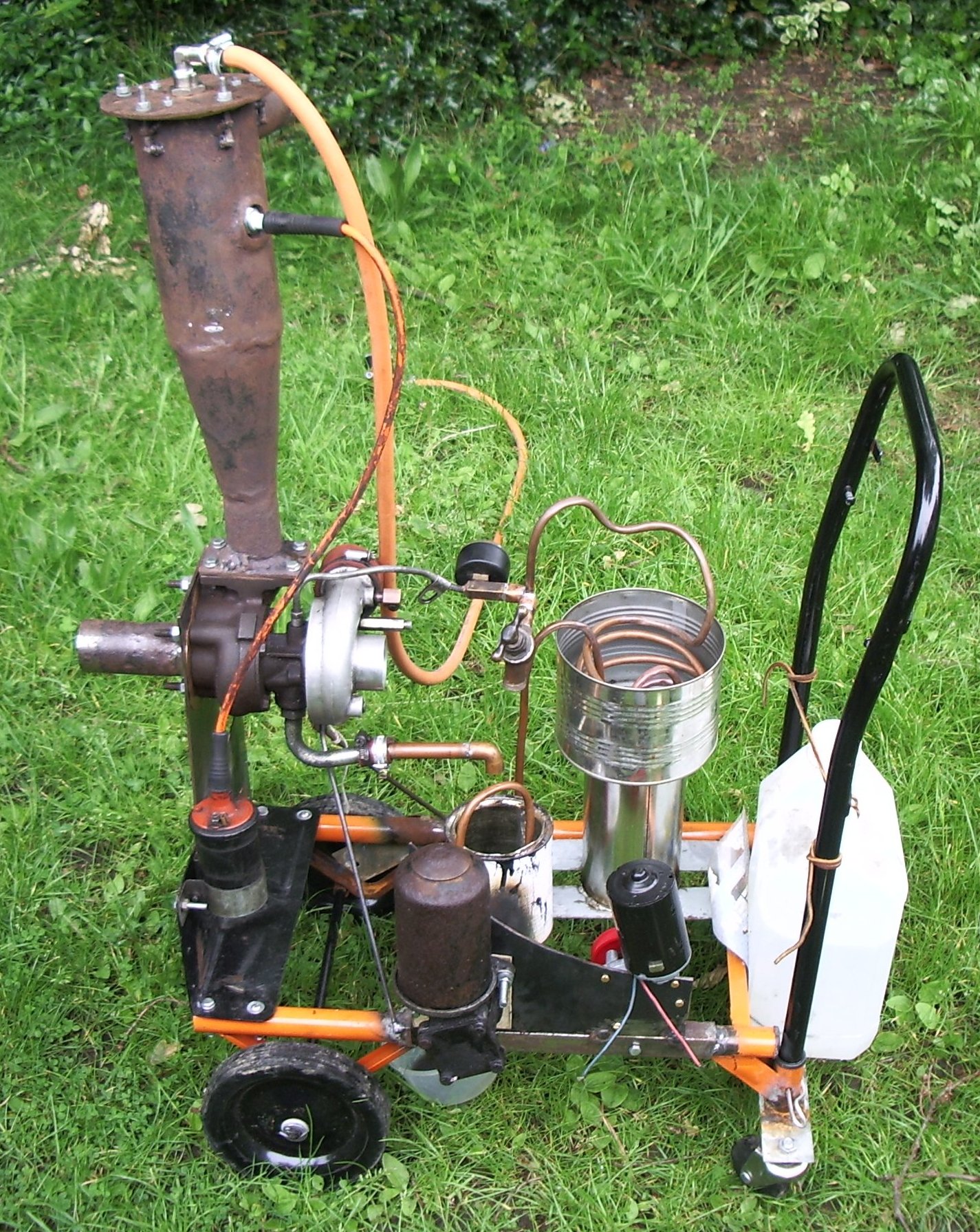
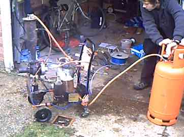
At this point there way a long period in which not much work got done on the jet for various reasons. I eventually got around to mounting the jet on a small trolley (made from some broken sack trucks) and added an oil pump and a few other things.
The first picture below is a general view of the jet as it currently exists. The ignition coil, combustion chamber and turbocharger have all been fixed onto the trolley. The large plastic container on the right hand side is just there as a counterweight to stop the trolley tipping from the weight of the turbo and combustion chamber at the other end. I plan to put the battery there to serve the same purpose while also providing power for starting and for running the oil pump.
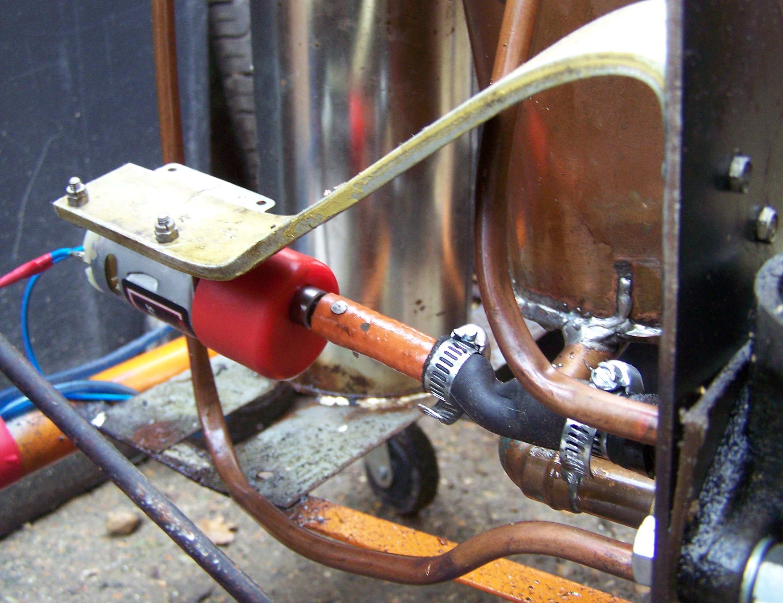
The second image shows the oil pump itself together with the motor that drives it. The pump is from some kind of ford and is driven by the windscreen wiper motor to the left of it. This pump was chosen mainly because it had the oil filter mounted on the pump rather than somewhere else on the engine. A belt goes from the large plastic pulley on the motor to the small brass one on the pump - this needs to be modified as it has a tendency to slip on the small diameter pulley. The pump is bolted to the same steel plate as the motor and pipes brazed to this plate provide the intake and outlet.
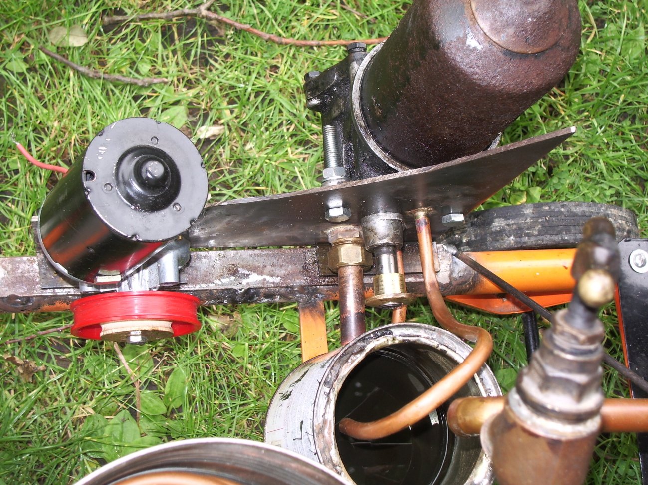
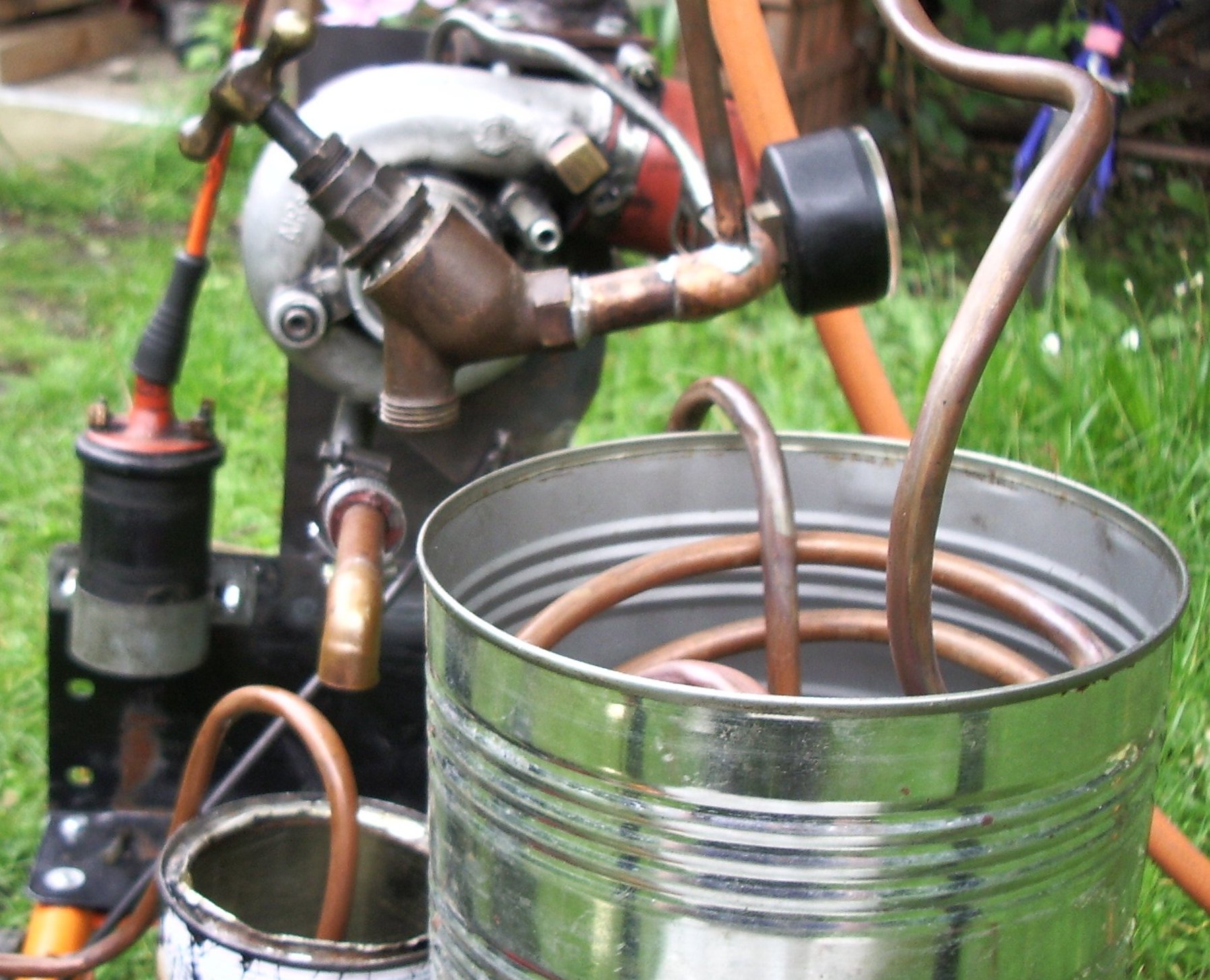
Three pipes connect to the oil pump. The first is a large diameter feed from the sump (conveniently made from an old pain tin). The second returns oil to the sump when the overpressure valve inside the pump opens. The third is the oil feed to the turbine. Then first picture below (also partly visible above) shows the arrangement for controlling the oil pressure and for cooling the oil. A piece of 10mm copper tubing leaves the oil pump and enters the shiny steel container, this is full of water to absorb the heat from the oil - since the oil passes through the turbine bearings and very close to parts heated by the flames it gets very hot. This tank can be initially filled with boiling water if it is necessary to preheat the oil to make starting easier but in use water evaporates from the container taking the excess heat with it. The length of tubing is sufficient that the oil leaves this heat exchanger with a temperature no higher than that of the water. Hence the oil feed is kept at or below 100 degrees centigrade even if the water begins to boil.
From here the oil goes to a tap that allows some oil to be returned to the sump to reduce the pressure. This tap is an ordinary household water tap modified to handle the hot oil. Its rubber seals have been replaced by a metal ball that can seal against the original valve seat and won't be damaged by the hot oil. There is also a threaded section taken from an old foot pump and a pressure gauge from the same is screwed in here. The oil then flows along a length of stainless steel pipe to the turbine. Oil pressure can be controlled by varying the position of the valve.
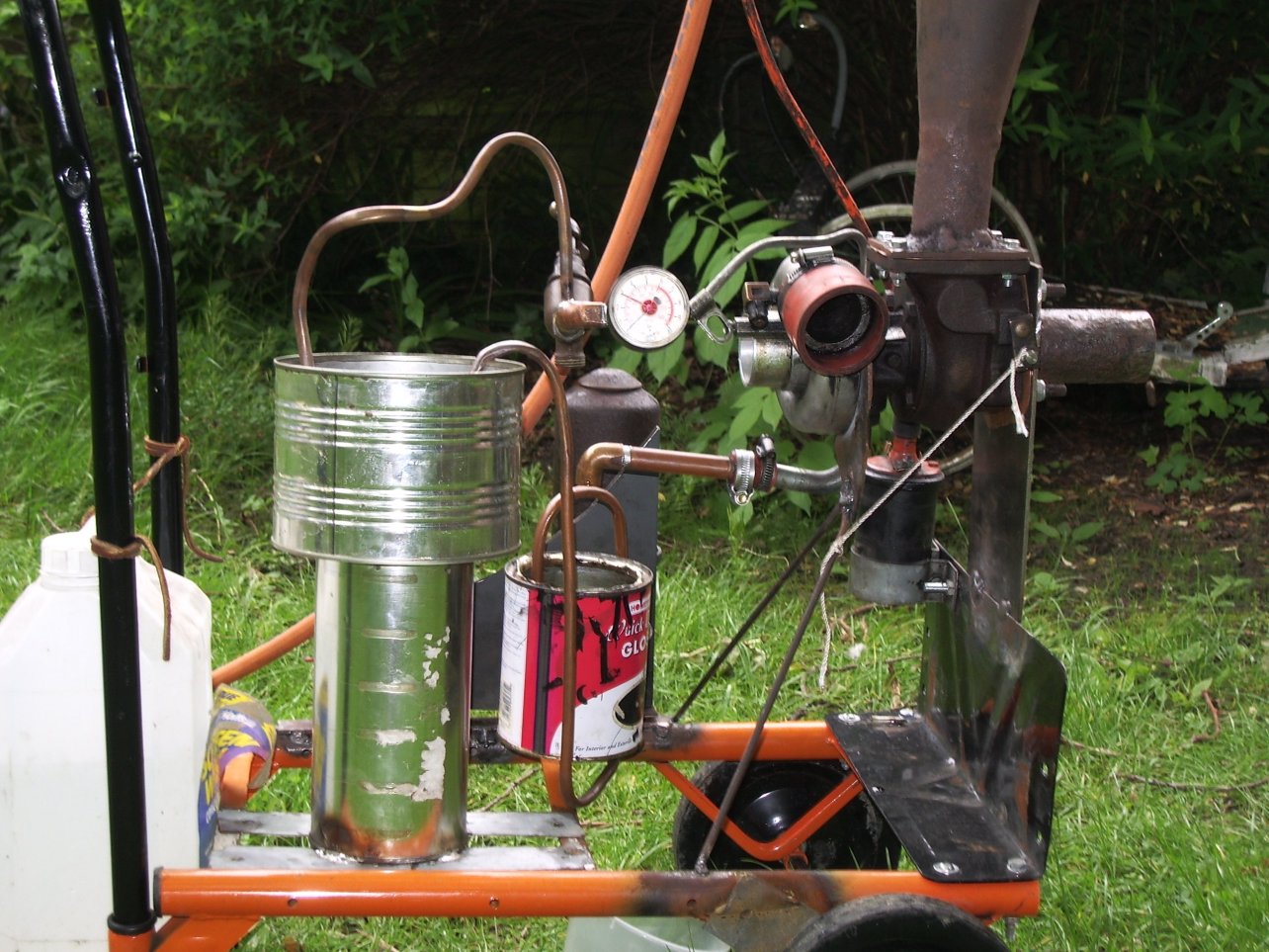
The last of the pictures above is just another general view of the jet on the trolley with many of the things just described visible. With all this set up several attempts were made to start the jet using a modified leaf blower as a source of air but no luck. Ignition was achieved easily but each time the leaf blower was unable to spin the turbine up to sufficient speed for it to self-sustain - every time the blower was removed the turbine started to slow and the fuel had to be shut off to prevent overheating the turbine. This problem could be solved with a much larger blower or by using a jet of compressed air to spin the blades of the turbine but to date neither have been tried.
December 2010
It Runs! After some fixes to the oil pump drive and a few attempts spinning up with a jet of compressed air the jet ignited and was spun up to a self-sustaining speed on propane. It ran this way with about 45 psi into the injector for about 30 seconds before the oil pump belt snapped again and the test was aborted. This test used a fairly thin oil mix composed of 20W50 engine oil diluted with paraffin. The next step now that I know it will work is to completely redo the oil system and run with a good synthetic oil that should stand up to the conditions in the turbo much better. At the same time various other things will be improved, an update will hopefully follow soon.
31st December 2010
Many of the changes and improvements have now been made and the jet was started and run for several minutes to record some video.
The oil pump motor was replaced with another geared to a higher speed allowing direct drive through a length of rubber tubing. Much of the oil plumbing was replaced, a boost pressure gauge was added and all the controls were moved to a single front panel. A short piece of copper pipe was also fixed into the intake to allow for easier starting than with a hand held blowgun. The last change was to build a new and improved driver for the ignition coil since the old one seems to have gone missing. This is described in more detail on the ignition page
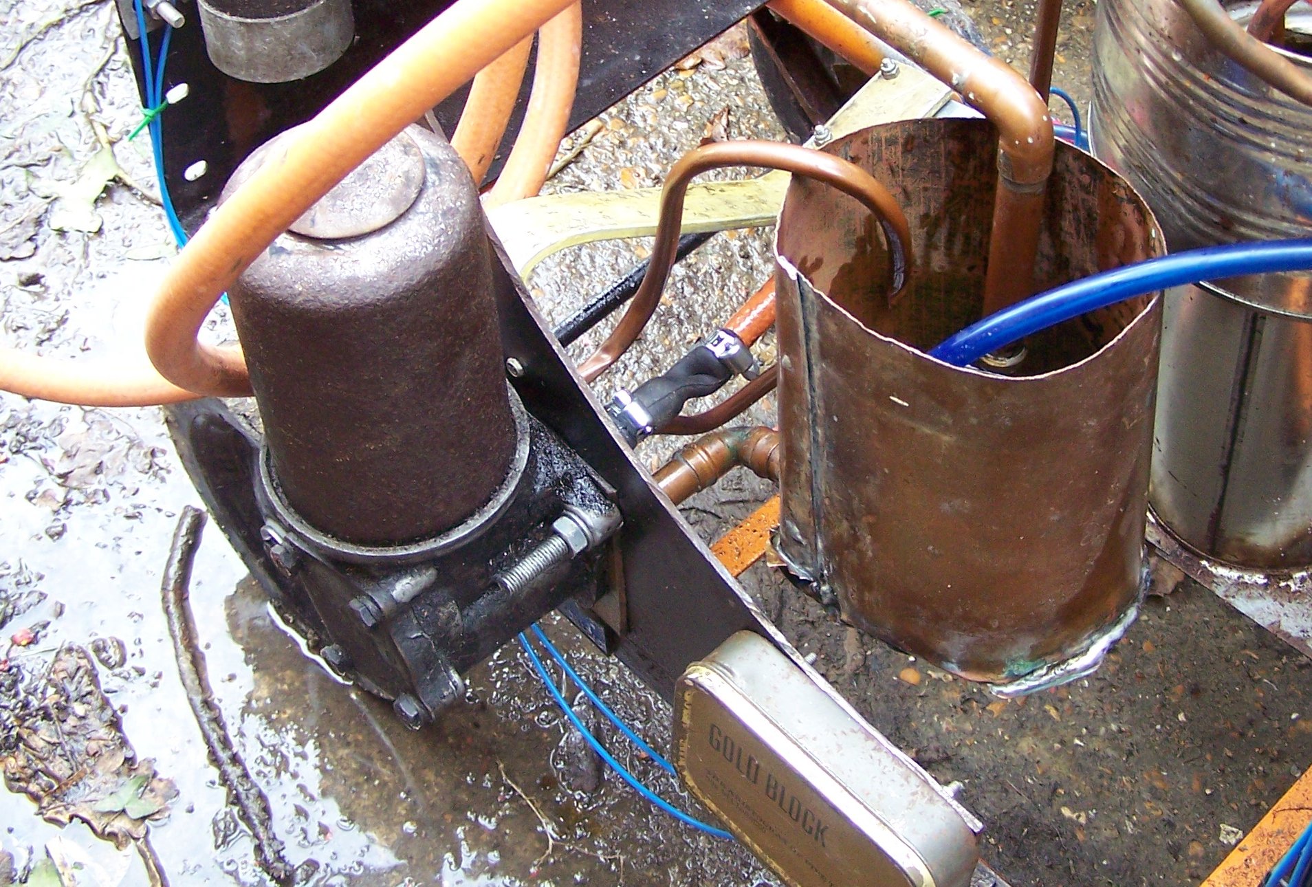
The above photos show the new oil pump arrangement with a new oil tank made from copper sheet which is hopefully less leaky than the paint tin although I think some of the leakage was around the oil pump shaft since in a car engine this does not need to be sealed as leakage here just trickles into the sump. The pipe from the bypass valve in the pump has been crimped shut to allow full manual control of the oil pump. The spare space where the original drive motor was has now been used to mount the ignition circuit in its protective tin.
This final photograph shows the new control panel, The switches from left to right are master (killing power to everything but the oil pump, including when fitted the propane cut off solenoid), oil pump, ignition, liquid fuel pump, and afterburner pump. The switch covers prevent the master and afterburner being turned on occidentally and this type also force the switches to the off position when closed over them. The top gauge is boost pressure, currently with a range of 0-10 psi which may need to be increased when the jet is run on liquid fuel. The bottom gauge is oil pressure 0-50 psi although the current oil and pump tends to limit the range to 3-20 psi hot, 5-30 psi cold. The knob to the left of this controls the oil pressure, the two terminals connect to the battery to allow use of an external power supply for long runs and the ball valve and quick release coupling at the far left control the compressed air for starting. Propane controls are on the cylinder as before. I found that since the propane regulator does not really work below 10 psi or so I needed to further limit the flow with the cylinder valve for starting. Once the jet had ignited it could be revved up to a boost pressure around 4-5 psi with a fuel pressure of 30 psi where it would self sustain and then with the propane at it's maximum of 50 psi the jet would run with just under 7 psi boost.
Click on the photo above for a video of the jet engine running!
Future plans for the jet are to add a liquid fuel system, a nozzle to generate some thrust, and an afterburner. Electronic measurement of exhaust temperature and turbine rpm will also be implemented (that's what the spare space on the control panel is for). After that of course I want to build a bigger one and mount it to a go-kart.