I actually built this fairly early on, before the combustion chamber (mainly because I was waiting for other parts and just wanted to start something). It is a simple circuit based on using a 555 timer to rapidly switch the supply of current to the primary of a car ignition coild on and off. It was built with components that just happened to be lying around - the resistor and capacitor values that set the frequency were not chosen with any specific values in mind but just with a rough order of magnitude estimate. It seems to be ok at what is probably a kiloHertz or two. There should be a frequency where the coil will produce the strongest and hottest spark and this could be found by making the resistor variable but I did not do this since it seemed to be 'good enough'.
A PNP transistor was used since this allowed it to be placed on the +ve side of the coil. The frame of the jet once this was constructed could then be -ve earth as standard on most cars without having to isolate the coil electrically from the frame. I will not add a diagram of this since there are so many ways of achiving this that it would be a waste of time. Anyone with the technical experience to attempt to build a jet engine should find the ignition design easy.
This is capable of producing a weak intermittant spark about 2 inches in length or a very hot powerful spark that can make thin electrodes glow red hot when the seperation is reduced to less than half an inch. It is also capable of setting fire to wood or just about anything else held in the arc with a suitably insulated impliment (seriously - dont try this one - it hurts when you get it wrong). The output of this circuit is at an extremely high voltage and while it should not do any major harm to healthy adults coming into contact with it is a still bad idea. I once got a shock from this circuit while holding a pair of pliers. After taking 30 seconds or so to recover I looked around for the pliers and eventually found them embedded in the wall a few inches from where my friends head had been.
New Ignition Driver
Since the old one went missing I built a new and improved driver circuit. Again this was based on a 555 driving a power transistor but this one should be more robust and perhaps a little more powerful.
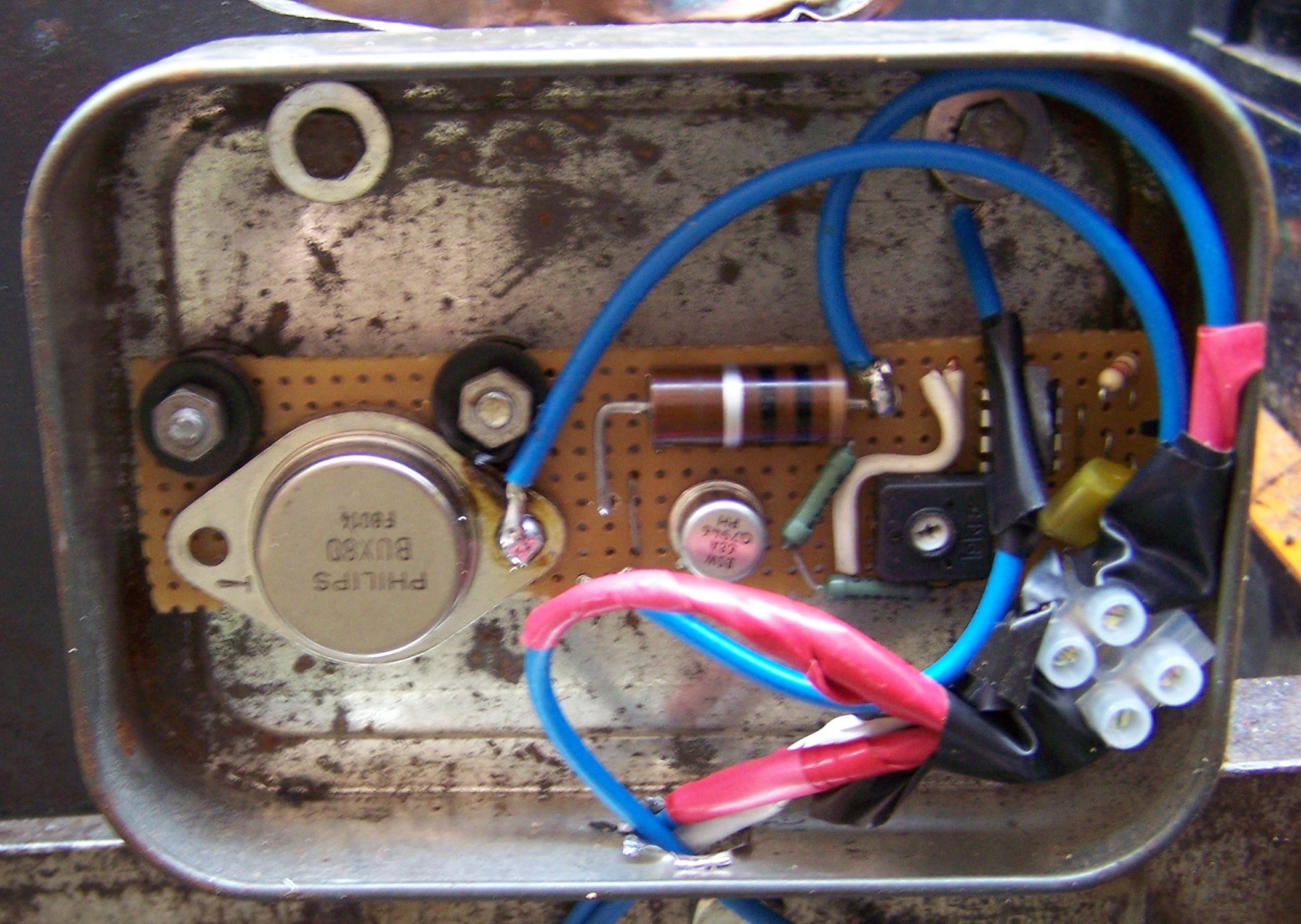
The output transistor used was a BUX80 which is designed for this kind of switching application and is rated at a maximum of 400 V. The other transistor is a medium power type rated at 1 A 150 V and was connected in this way with the 10 ohm collector resistor rather than in standard darlington configuration because 1) this means that it does not see the same peak collector voltage as the output transistor and 2) is allows the output transistor to saturate reducing its power dissipation. The circuit was built on a piece of stripboard and mounted in an old tobacco tin as can be seen in the photo below.