Current status (2024): Archived / obsolete
This project is unlikely to resume, but for some reason this page seems to get a lot of traffic so I shall keep it up.
It was an interesting excercise in building power transformers, but today I just wouldn't do it this way, I've learned a lot about power electronics since then, and a more modern SMPS approach would be far more achievable than it was when I initially started this. Also, the price of plasma cutters has fallen, to the point where I bought one with a built in compressor for £150 from a well known German discount supermarket. It just doesn't make sense to build one today, and certainly not a big, crude, oil-filled lump like this.
Plasma cutter legacy content
I had been wanting a plasma cutter for a long time but they're very expensive and the cheaper ones can only cut fairly thin metal. The idea was to build the power supply side of a plasma cutter and make it work with a cheap Chinese torch bought on Ebay. Essentially what's needed is a power supply that can deliver several hundred volts d.c. open circuit but when loaded deliver a constant current somewhere in the region of 40-60 amps. It also needs to include a high frequency circuit to strike the arc and various other bits and pieces to make the torch cut.
All images on this page are low resolution versions. Click them for bigger versions (may take some time to load)
The most important part of the plasma cutting power supply is the transformer. This was actually made up of six microwave oven transformers with rewound secondaries. The transformers used were all from 800 or 850 W microwaves and hence are designed to handle about 1 kW each (the commonly stated power rating of a microwave oven is the microwave output power not the input to the transformer). The welds holding the E-I laminations together were cut through with a hacksaw and the high voltage secondary winding removed.
The new secondaries were 35-40 turns of 2 mm diameter enamelled copper wire wound around home-made cardboard bobbins. The magnetic shunts were left in place in the transformers to assist in limiting the current. The transformers were then clamped together, tested (with a few feet of thick steel fence wire across the output as a high current load), and then arc welded back together.
The six transformers were then welded to a length of steel box section which was then bolted to the top half of a 25 litre acetone drum which had but cut in two about 2/3 of the way up. The secondaries we then connected in series and the primaries in parallel before the drum was reassembled with the transformers inside and the join sealed with soft solder. The drum and transformers were then carefully dried and the drum was filled with about 22 litres of ASDA smart-price engine oil (transformer oil would have been better but much more expensive). The oil provides both cooling and insulation for the transformers.
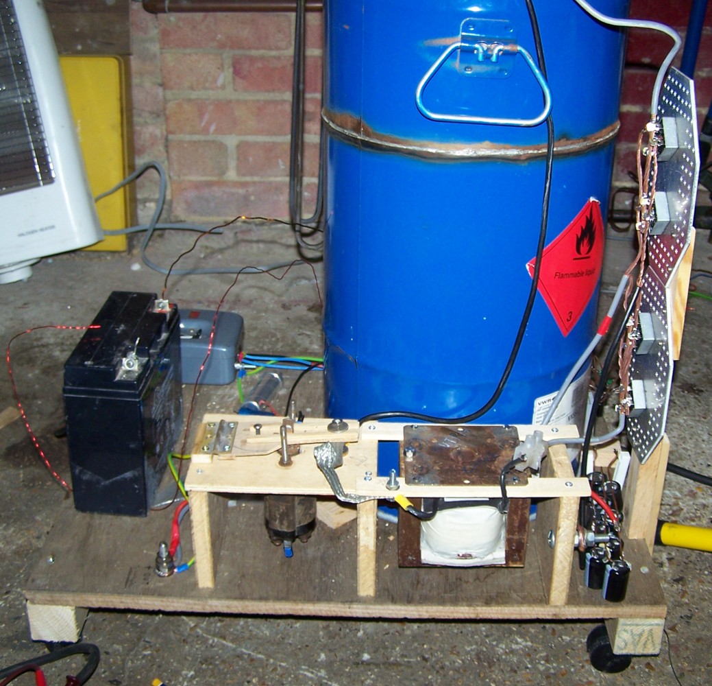
The second of the two pictures above shows the transformer drum now filled with oil and mounted on a wooden trolley. At some point in the future better wheels will be added to allow the plasma cutter to be moved across rough ground. Also visible is another rewound microwave transformer and rectifier that supplies 12 V d.c. to various bits of control circuitry, a metal-case switch-fuse that controls incoming power and a homebuilt solenoid switch that switches the output of the transformers.
The photographs below show the rectifiers, output switch, and soft start circuit. The four 35 A bridge rectifiers are mounted on two octagonal aluminium heatsinks. The connections to these are arranged to have equal resistances in order to allow load sharing between them. Transformer output reaches these via the output switch and an ac ballast inductor which limits the current by an adjustable amount (adjustment is by altering the air gap). The inductor is wound on another microwave oven transformer core using the same wire as for the transformer windings. The Output switch is made from two bronze contacts, some flexible high current braid and a solenoid from a starter motor. The contacts in the starter solonoid were not used since they are not designed to break a circuit with this amount of voltage and could easily arc on opening. The homemade switch separates the contacts by a much greater distance in order to ensure the arc is rapidly extinguished.
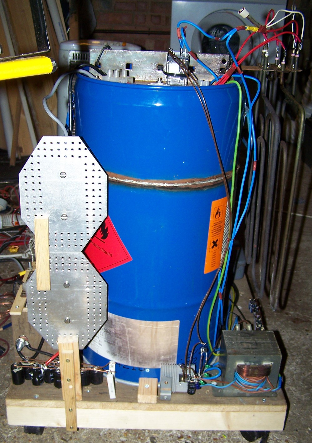
Also visible above are some smoothing capacitors for the main output with bleeder resistors, the rectifier for the 12 V control circuitry, and the soft start circuit which closes the large relay several seconds after switch on shorting out the heating elements used to limit the initial inrush current.