Stacking normal bench supplies in series or hanging rectifiers off the mains gets a bit tedious and is less safe than it could be with a dedicated HV bench supply. I wanted something suitable for valve projects, prototyping with power electronics, etc. Basic spec is 0-500 V 0-100 mA CV/CC. I might make it able to do 200 mA at less than 250 V. Should also have a low current negative bias output and a selection of useful heater voltages. At the time of writing (June 2015) this is partially completed.
All images on this page are low resolution versions. Click them for bigger versions.
Design Description
I wanted a rugged and reliable design but with good regulation and current limit performance. This leads to a fairly conventional design with multi-tapped 50 Hz transformers and a series regulator. The bulk of the PSU is semiconductor based but the pass elements and their driver will be valve.
I want a PSU where I can short the output when on maximum volts and it cleanly enters current limit without killing the output devices. I spent a while looking at the semiconductor options here but second breakdown bites hard in this region. The closest I came was a design with series-stacked NPN bipolars and I still couldn't convince myself they wouldn't go pop the first time they saw a short circuit. This leads to the use of TV line output pentodes instead. The PL504 has been chosen partly for its specifications and partly because it is dirt-cheap. PL519s have a much higher rated anode dissipation and wouldn't have required a parallel pair but they're rarer and more expensive. The current limit no longer needs to be blazingly fast (and probably foldback), if it's leisurely then the anodes may simply flash red for a fraction of a second until the tap-changer operates to reduce dissipation. The negative supply at only 200 Volts and a few milliamps can safely be semiconductor, particularly as it can have enough series resistance to limit the peak current if it is short circuited.
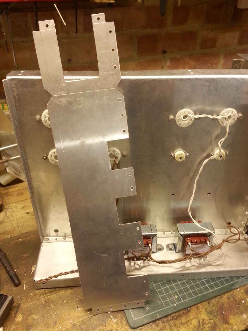
An EF91 is used to pull down the control grid of the pass valves, another as a 1 mA current source for it to pull against. The lower one sees almost the full unregulated HT plus the negative bias supply. That means its anode Vmax is exceeded a little but the current (and hence the dissipation) are very low. The only real danger here is flashover outside the glass between the B7G pins. If kept clean and dry it is likely never to cause any problems but purists might prefer to substitute a small valve with a top-cap anode here, perhaps a TV shunt regulator such as a PL81.
In addition to the main HT transformers there are a variety of floating supplies for heaters, the pentode screens and various bias supplies. In hindsight I should have used a high frequency transformer for these, perhaps something based around a halogen lighting “electronic transformer”. That would have considerably reduced the amount of iron in the design and I may yet rework some bits to do that.
Chassis
With lots of transformers, some valves and socketed relays the design lends itself to a traditional chassis style of construction. The cross-section is approximately an asymmetric inverted T shape. The general idea was to keep all the high power stuff on one side and the control and wiring on the other. The high power side will then be closed off with mesh or punched sheet, the other side with solid sheet.
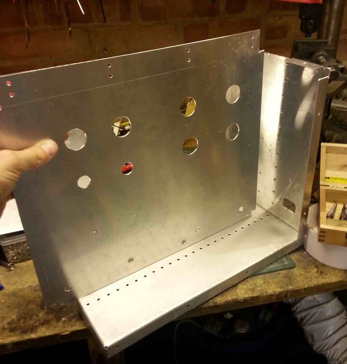
The chassis is made from several sheets of aluminium, the middle being thicker as it needs to maintain its strength when drilled with many large holes. A combination of pop rivets and nutserts are used in the construction. Large holes were made with a step drill although Q-max cutters are also very good for this.
Front Panel
The front panel will hold the output terminals, controls and metering. I have a preference for digital voltmeters and analogue ammeters. At the time of writing this part has yet to be completed but will probably be built up from various ebay DVM modules and 100 uA meter movements suitably rescaled. I do have quite a few more of the edge view meter movements used in the mains frequency meter but these take a lot of depth inside the case.
Power Section
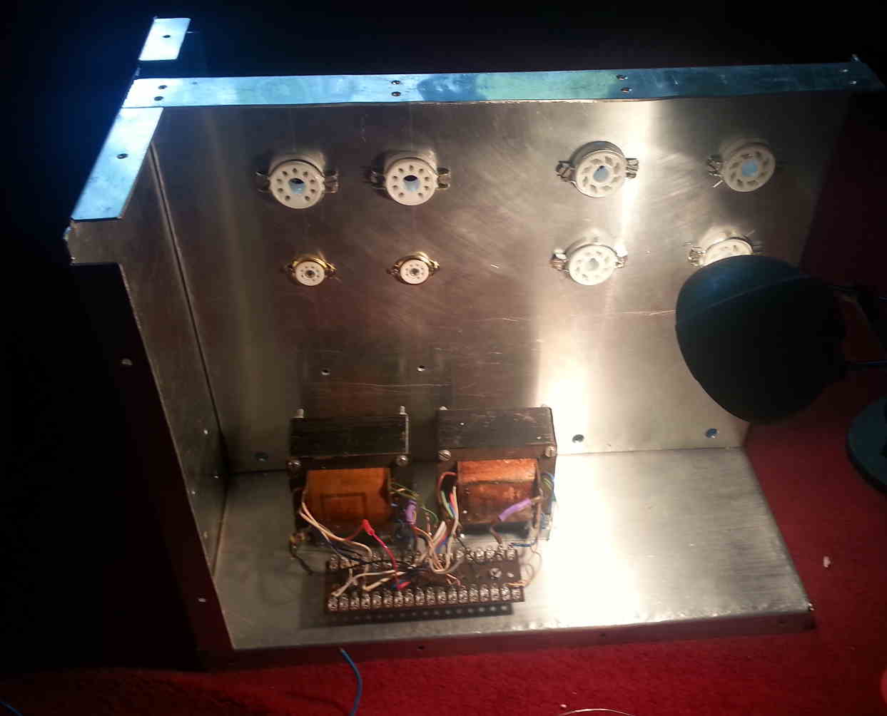
This consists of the two main transformers (300V 100 mA + a few other windings, from Grundig tape recorders), the 4 valves and the 4 relays. The transformers were originally equipped with selenium bridge rectifiers and therefore do not have centre taps. These are the transformers visible in the photo above. One relay shorts a primary-side resistor after a short time providing some degree of soft-start. The second relay puts the two secondaries in series or parallel. The third shorts out a pair of secondary-side power resistors which are before the pass valves (one for each transformer). These resistors drop about half the transformer voltage (so around 150 V) at 100 mA. This relay operates in conjunction with the series-parallel selection to provide 4 stages which minimise the dissipation in the pass valves. The final relay connects the output to the front panel terminals.
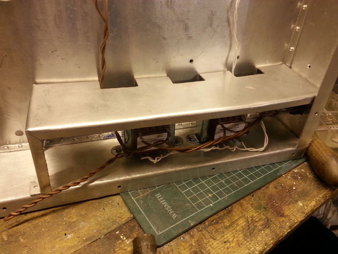
Currently two dual-15 V transformers provide a floating 60V AC supply for the heaters of the two PL504s and the upper EF91 which are all wired in series, this supply is tied to the PL504 cathodes to limit Vhk. Also hanging off of here are step-up transformers which generate the -200 V bias supply and the screen supply. This part of the circuit may get replaced by a high-frequency transformer of some kind.
Negative Supplies
Two regulated negative supplies are generated. One variable 0-150V with a current limit of a few milliamps, this is the bias supply available on the front panel. The other is fixed -200 V and is used internally. This is the rail that the grids of the pass valves are pulled down towards by the final EF91. These rails have simple voltage-follower type semiconductor regulators with series resistance and current limit to ensure the transistors stay inside their safe operating area at all times, including when charging capacitors, etc.
Since the cathode of this lower EF91 must be at -200 V a separate heater supply is required. This is also used to generate a local bias supply of a few volts below cathode for its grid allowing it to be controlled with an optoisolator. The main control circuitry can then be referenced to the 0 V rail at chassis potential.
Control
The control section is all semiconductor. It includes a timer for the soft-start relay, op-amps for the voltage and current control loops, and logic to control the tap changing relay based on output voltage and therefore pass element drop. It is also intended to include thermal shut-down based on transformer temperature and possibly also on anode infra-red emission.
Miscellaneous
Additional floating supplies for panel meters, shunts and op-amps for current sensing, etc.